42 ct shorting terminal block wiring diagram
To connect the CT lead wires to the CT input terminals, first strip about 1/4″ (6 mm) of insulation off the end of one of the wires, twist the bare strands together, insert the end into the terminal block, and tighten the screw securely. It will be easier to connect the wires to the terminal block if the block is first plugged into the meter. Jan 19, 2019 · CT cable was a spare cable and shorted at the terminal . Wiring Diagram / AC Schematic Information. Terminal Blocks may have Shorting Capability, but CT Circuits can pass through have some Wiring Diagram information shown on them. Schematics and.This kind of picture (Transformer Block Diagram Luxury Current Transformer Connection Diagram Ct ...
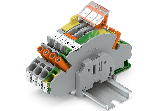
These shorting blocks are designed to be a superior alternative to the traditional shorting block. They uniquely have captive hardware to prevent lost grounding screws. This design protects against errors, insuring inherently safer installation or removal of meters from service. The CT shorting blocks indicate clearly when the screw is engaged

Ct shorting terminal block wiring diagram
Once the current transformers are properly shorted using the CT shorting block, it is safe to make wiring modifications on the meter side of the shorting block. Once the intended wiring modifications have been completed, you will need to remove the shorting screws from the positive CT lead terminals in order to return the meter to proper operation. The secondary leads run to a shorting terminal block somewhere in the circuit. As mentioned, 4 and 6 pole blocks are common. 12 pole blocks are also used. Most metering rated CT's come with a shorting bar installed that can be closed with a sliding jumper to allow for work on wiring while the CT's remain energized. Using a 6 pole shorting bar as an example, three terminals are wired to CT ... ct shorting terminal block wiring diagram. Ct Shorting Block Wiring Diagram Oleh Anonim Mei 14, 2020 Posting Komentar Demonstration of shorting a ct shorting block for safe wiring modifications. The screws connecting the conductors are only accessible after the current transformer has been short circuited using the short circuit slider.
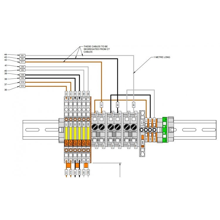
Ct shorting terminal block wiring diagram. Open Circuit CT's. DANGER: Current transformers should remain shorted until connected to a secondary circuit. CTs are typically wired to a terminal block where shorting screws can be installed to tie isolated points together. It is important that a CT always have a burden or load connected when not in use, otherwise a dangerously high secondary voltage can develop across the secondary terminals. disconnecting or disturbing the wiring. The sliding link terminal blocks open up the circuit and also can be equipped with either a two position or four position sliding jumper that provides a short to adjacent terminal blocks, typically used in current transformer, CT circuits. > The current transformer secondary is short circuited during the operation. > What is the reason, and explain with details. (CT) is a type of instrument transformer specially designed for protection and measuring purpose, it will operate by the current whenever it exceeds the set value. The C.T converts the 1000A/5A. Short Form Catalogue Terminal blocks Gross Automation (877) 268-3700 · www.entrelecsales.com · sales@grossautomation.com guideBU_1-2 040206 1SNC 160 003 C0205
Ct Shorting Block Wiring Diagram from newwiremarine.com Print the electrical wiring diagram off plus use highlighters to be able to trace the circuit. When you employ your finger or even stick to the circuit together with your eyes, it is easy to mistrace the circuit. 1 trick that I actually use is to printing exactly the same wiring diagram ... Current Transformer Shorting CTs should remain shorted during installation until secondary wiring is complete. Figure 4 shows the termination of a multi- ratio CT on a shorting terminal strip. A shorting screw inserted through the shorting bar ties isolated terminal strip points together. Any shorting winding effectively shorts the entire CT ... 1000+ wiring diagram schema current transformer wiring diagram & instructions note: we supply these meters on the assumption that they will be installed by a qualified electrician familiar with the installation of metering equipment ensure all current transformers are installed as per wiringdiagram (which can also be found under the terminal cover of the meter),thecorrect polarity of current transformers is essential ie ...
CT Shorting Block provides current transformers, potenetial transformers and shorting blocks to industry and utilities companies. CT Shorting Blocks, a critical part of current transformer protection. Current transformer shorting blocks protect not only equipment, but personnel. We stock 4,6 & 8 Point Shorting Blocks. Connectors: #14 - 4 mechanical connectors provided for ease of connecting CT wires. If ring terminal is desired, use U prefix rather than UC. Terminals: Range of 5 to 13 terminal block assemblies available to meet most of your single- and three-phase application needs. Ringless/Ring Type: Units available in both ringless and ring type styles. ct shorting terminal block wiring diagram. Ct Shorting Block Wiring Diagram Oleh Anonim April 17, 2020 Posting Komentar Demonstration of shorting a ct shorting block for safe wiring modifications. The screws connecting the conductors are only accessible after the current transformer has been short circuited using the short circuit slider. TERMINAL MARKINGS AND INTERNAL WIRING DIAGRAMS SINGLE PHASE AND POLYPHASE MOTORS MEETING NEMA STANDARDS See Fig. 2-11 in which vector 1 is 120 degrees in advance of vector 2 and the phase sequence is 1, 2, 3. (See MG 1-2.21.)* MG 1-2.24 Direction Of Rotation
600 VAC Shorting Terminal Block, 8-Pole | Veris Power ...
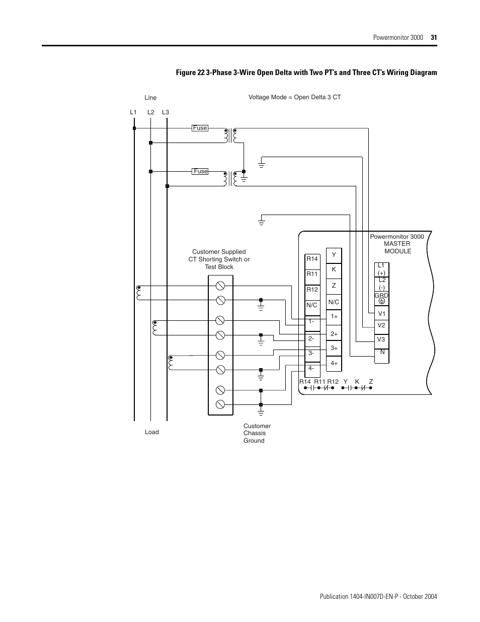
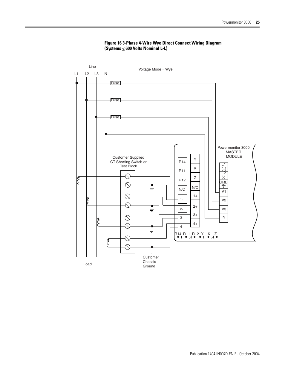
Terminal. Example a CT with a Class 0.5 VA rating of 1VA will need 2.5mm2 cable if the CT secondary cable is between 0.5 and 1.9 meters long. HEX-S0000-PM3255-4WY3CT-00 PM3255 4 WIRE WYE 3CT DIRECT CONNECTION DIAGRAM 0 11/09/2019 Version 1.0 CVR CT shorting and disconnect terminal instructions METER METER CONNECTED TO CTs CT SHORTED AND METER ...

CT Shorting Blocks in stock for quick delivery
On this website we recommend many pictures abaout Ct Shorting Block Wiring Diagram that we have collected from various sites Wiring Diagram – strategiccontentmarketing.co, and of course what we recommend is the most excellent of picture for Ct Shorting Block Wiring Diagram.If you like the picture on our website, please do not hesitate to visit again and get inspiration from our website.

What is the purpose of a magneto shorting block
Demonstration of shorting a CT shorting block for safe wiring modifications.To learn more, please visit the Schneider Electric FAQ:http://spr.ly/60558E0gW Su...

Colin's Diner is a small train car in New Canaan, CT, that was later converted into a small diner, with nice aesthetic.
May 11, 2020 · Demonstration of shorting a ct shorting block for safe wiring modifications. The screws connecting the conductors are only accessible after the current transformer has been short circuited using the short circuit slider. Ct Shorting Block Wiring Diagram . Ct installation and wiring explained by continental control systems.
Disconnecting Terminal -Ready to Wire in CT Secondary ...
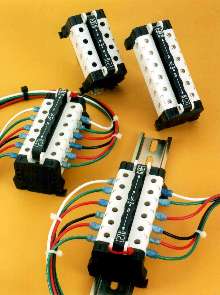
Wiring Diagrams DANGER Only licensed electricians who have appropriate training and experience with high voltage and current devices should install and wire the terminal block assemblies. The following diagrams illustrate how to wire the terminal block assemblies to the electrical system and to the power meter.

IKU6SC GE / General Electric 6 POINT SHORTING TERMINAL ...
CT Shorting Terminal Strips The illustration below shows the termination of a multi -ratio CT on a special shorting terminal strip. Insertion of shorting screw through shorting bar ties isolated terminal strip points together. Any shorted winding effectively shorts the entire CT. X1 X2 X3 X4 X5 Startco MPU -16 Motor Protective Relay Retrofit installation in draw-out case. Startco Engineering ...

CTB-3 secondary overvoltage protection of the wiring ...
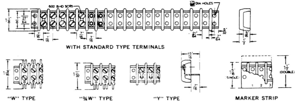
Terminal Connections All required terminal hardware is supplied with every FT Switch (see Figure 5). Screw terminals are provided standard with all FT switches. Connections are made with a hex washer head screw - #8 thread size (0.164-32), 1/4" hex head. Stud and nut terminals are an optional feature. Connections are made with two washers and ...

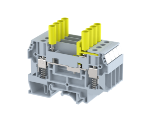
Spring Clamp Sliding Link Terminal Blocks
Find Ct Shorting Block Wiring Diagram Manufacturers & Suppliers from China. We are Professional Manufacturer of Ct Shorting Block Wiring Diagram company, Factory & Exporters specialize in Ct Shorting Block Wiring Diagram wiht High-Quality.

Equivalent Circuit Disconnect Shorting Terminal Blocks
This Test Block is the sort of thing we usually use. This one is from Owen Brothers, in Oldham. I think you can get an idea from the photos of what they do. There are shorting links for the CT connections, and disconnecting links for the voltage connections. The model I have linked to also has 4mm sockets for test connections to the voltages.

Model# 17SC Shorting Terminal Block | FLEX-CORE®
Safe current and voltage transformer wiring with a single terminal block system. Integrated single-stage forced short circuit mechanism for 100% safe handling. Dedicated cross-connection channel before and after the disconnect contact for maximum flexibility. Test sockets allowing adjoining fully insulated test plugs up to 10 mm diameter.

Test Terminal Blocks - Installation Equipment
Find Ct Shorting Terminal Block Wiring Diagram Manufacturers & Suppliers from China. We are Professional Manufacturer of Ct Shorting Terminal Block Wiring Diagram company, Factory & Exporters specialize in Ct Shorting Terminal Block Wiring Diagram wiht High-Quality.

Vantage - SHORTING BLOCK-SIX TERMINAL SHORTING BLOCK
current applied. Wiring between the CTs and the power monitor should include a shorting terminal block in the CT secondary circuit. Shorting the secondary with primary current present allows other connections to be removed if needed. An open CT secondary with primary current applied produces a hazardous voltage, which

Accessories Downloads - Electro Industries/GaugeTech
ct shorting terminal block wiring diagram. Ct Shorting Block Wiring Diagram Oleh Anonim Mei 14, 2020 Posting Komentar Demonstration of shorting a ct shorting block for safe wiring modifications. The screws connecting the conductors are only accessible after the current transformer has been short circuited using the short circuit slider.

Ct Shorting Block Wiring Diagram - Wiring Schema
The secondary leads run to a shorting terminal block somewhere in the circuit. As mentioned, 4 and 6 pole blocks are common. 12 pole blocks are also used. Most metering rated CT's come with a shorting bar installed that can be closed with a sliding jumper to allow for work on wiring while the CT's remain energized. Using a 6 pole shorting bar as an example, three terminals are wired to CT ...
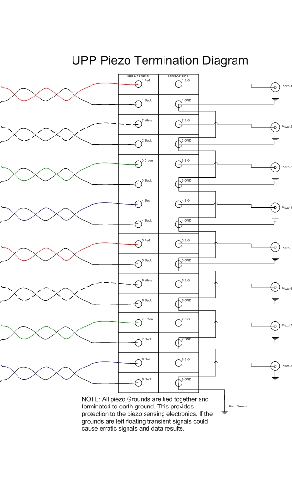
Print Article - Piezo Termination for UPP units.
Once the current transformers are properly shorted using the CT shorting block, it is safe to make wiring modifications on the meter side of the shorting block. Once the intended wiring modifications have been completed, you will need to remove the shorting screws from the positive CT lead terminals in order to return the meter to proper operation.

CT Shorting Blocks in stock for quick delivery

Shorting kits now available for current transformer ...
Terminal Block uses one switch to shunt secondaries.

CT Shorting Blocks in stock for quick delivery

CT secondary overvoltage protector - Products - Electrical ...

Wiring Diagram Terminal Block - Wiring Diagram Schemas

Shorting Terminal Block | Circuit Disconnect Terminal Block

CT Shorting Blocks in stock for quick delivery

Why is the secondary of the current transformer never used ...
Terminal Blocks .::. Renfrew Electric Terminal Blocks

World in Motion
Ct Shorting Block Wiring Diagram - Wiring Schema

Pier 86 grain terminal at sunset, Seattle, WA.

Ct Meter Wiring Diagram | schematic and wiring diagram

Electrical Connections | Basic Electricity Worksheets
Ct Shorting Block Wiring Diagram - Wiring Schema

Grand Central Terminal during COVID19 Pandemic

Sliding Link Terminal Blocks, Shorting Blocks
Current Transformer Terminal Blocks Added to WAGO's Rail ...

Phone Terminal Block Wiring Diagram - Wiring Diagram

Equivalent Circuit Disconnect Shorting Terminal Blocks

1504 SC 72769 MARATHON 4 POINT SHORTING TERMINAL BLOCK ...

e-Train - TCA, Toy Trains, Train Collectors Association
Is a small current transformer (Talema AC1005) with 2 amps ...
WAGO COP3 HV/LV ENCLOSURE 3PH 3 WIRE - NO NEUTRAL (50079591)

The CTB-6 current transformer secondary overvoltage protection
KW1M-H Eco-POWER METER Dimensions | Automation Controls ...
0 Response to "42 ct shorting terminal block wiring diagram"
Post a Comment