45 lvds wiring diagram
If there are two LVDS cables between th T CON d th M i b d th 2nd P 12V the T-CON and the Main board, the 2 LVDS will not carry any voltages. It will also have fewer pins. ower Supply 12V Main Board T-CON 12V switch on in the 2nd step of the turn-on process Be First, Do it Right, Work Smart! 11 March 2012 LCD T-CON Troubleshooting on process. LVDS data wire: LVDS stands for "Low Voltage Differential Signalling". There is always an LVDS data wire between the control unit for the display and the screen (except E83, E85, E86): LVDS is a special technology for fast and secure data transmission: There are 2 wires for each signal.
SATA/150 - first-generation of Serial ATA interfaces, run at 1.5 Gigahertz (GHz). Actual data transfer rate is up to 1.2 Gigabits per second (Gb/s), or ~150 megabytes per second (see the notes below for the actual transfer rate). The simplicity of a serial link and the use of LVDS allow to use of longer drive cables.

Lvds wiring diagram
Wiring diagram for BMW CIC A. Screen unit-replace the OEM screen. B. Power and audio connectors-connect to the OEM head unit (NOTICE the fiber optics plug, see the next page). C. Connect to original harness which unplug from OEM head unit. D. LVDS plug-connect to the LVDS cord which removed from OEM screen (NOTICE if you don't 1.2VDS - Low-Voltage Differential Signaling L The 350 mV typical signal swing of LVDS consumes only a small amount of power and therefore LVDS is a very efficient technology, delivering performance at data rates up to 3.125 Gbps. The simple termination, low power, and low noise The diagram above illustrates the use of the Chipset (Tx/Rx) in a Host to LCD ... This feature enables you to overcome cable capacitance through the LVDS ...
Lvds wiring diagram. SLLA053B 4 Performance of LVDS With Different Cables GND Y Z I = 3.4 mA A Figure 1. Simplified Circuit Diagram of Transmitter 2.2 Transmission Line Since the output of the SN65LVDS31 driver changes state in about 500 ps, an interconnection to The problem that I am having is with the 30-pin cable. I found the pin diagram for the monitor, and also the pinout on the MT6820-B, but the abbreviations for the outputs/inputs are completely different on each. I was hoping that perhaps someone might be able to help match them up so I don't fry the monitor. Wiring Diagram 6-1. Wiring Diagram - Main Board CN600 IP-Board → Main CN400 LVDS Connector (Main → Panel) CN703 CN102 CN101 CN501 OP700 CN801 CN821 HDMI Jack DVI jack PC jack Audio/Optical Out ... Abstract: LTM170E6-L04 pcb diagram inverter samsung lcd monitor lcd LVDS display 14 pin connector fujitsu NEC lcd 17 VGA CABLE CONNECTION DIAGRAM pin ...
Abstract: LTM170E6-L04 pcb diagram inverter samsung lcd monitor lcd LVDS display 14 pin connector fujitsu NEC lcd 17 VGA CABLE CONNECTION DIAGRAM pin ... [LVDS cable] with connector for wiring between devices A combination example of Hirose MDF76 connector and [LVDS cable]. Used for transmission between image processing such as LCD (liquid crystal panel) and LCD monitor. 1.0mm pitch board-to-cable LCD interface connector with the high-speed transmission, EMI protection, and strong mating retention. LVDS and M-LVDS Circuit Implementation Guide by Dr. Conal Watterson Rev. 0 | Page 1 of 12 INTRODUCTION Low voltage differential signaling (LVDS) is a standard for communicating at high speed in point -to-point applications. Multipoint LVDS (M-LVDS) is a similar standard for multi-point applications. Both LVDS and M-LVDS use differential Rear view connection diagram . LVDS converter extras kit connection diagram . Installation and cabling diagram . To install the rear view with button and control unit . To route and connect the rear view wiring harness . To connect the power supply and connection cable . To install and connect the LVDS converter . Concluding work and coding
Universal LCD/LED TV Controller Boards Schematic Diagrams. Here are the schematic diagrams document for the following few universal LCD/LED controller mainboards for a better understanding of circuit diagrams and block diagrams: TP.VST59S (TSUMV59S) Schematic Diagram. CV801LE-A-15 Schematic Diagram. SLLD009—November 2002 LVDS Application and Data Handbook 1-1 Chapter 1 Data Transmission Basics Data transmission, as the name suggests, is a means of moving data from one location to another. LVDS circuit between radio and display receiver assembly and stereo component tuner assembly ; ... this DTC may be stored depending on the battery condition or engine start voltage. WIRING DIAGRAM. CAUTION / NOTICE / HINT. NOTICE: ... System Diagram The prototype connects the LVDS output of the SOC and the LCD-display using free-floating enameled copper wire. My questions: Can a LVDS generally produce a "rather" correct image using this kind of wiring? Or is a LVDS twisted-pair connection mandatory? I have tried to visualize the LVDS signals using an oscilloscope, with no success.
Original Lcd Lvds Video Display Screen Webcan Flex Cable For Hp 14 Am Hd 14 Ebay
How to Make a 30 Pin LVDS cable for connecting the display panel and a universal LED TV board. Through the LVDS cable, there are various ...

Vstt56u11ledlcdtvuniversalmotherboard Lvds Connection For Led Tvpanel Youtube
Low-voltage differential signaling, or LVDS, also known as TIA/EIA-644, is a technical standard that specifies electrical characteristics of a differential, serial signaling standard, but it is not a protocol. LVDS operates at low power and can run at very high speeds using inexpensive twisted-pair copper cables. LVDS is a physical layer specification only; many data communication standards ...

Jual Kabel Flexible Laptop Lvds Cable Samsung Nc108 Nc110 Np Nc108 Nc108p Ba39 01057a Di Lapak M2m Notebook Bukalapak
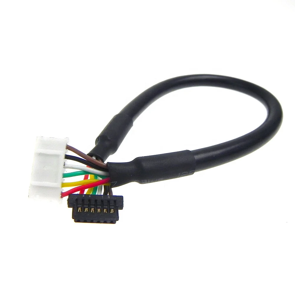
Installation Diagram LVDS Cable from Vehicle Left Front Speaker USB Rear View Camera Input GPS Antenna S1C016A-Y03E Navigation Map SD. 2 Installation Parts 1 Power T-Harnesses 4 GPS Antenna 2 LVDS Cable 5 USB extension 3 HDMI Cable 6 Rear Camera Input 7 Interface Module 2 1 4 3 6 5 7. Factory Radio HMI Module LVDS LVDS Cable
Data Modul Com
Led Tv Board Schematic Diagram. Are you a technician? Do you repair Lcd Led Tv? If yes then I have a gift for you that is LCD/LED Tv Board Schematic Diagram.Today I will give you a Collection of All Smart Universal Brands Lcd Led Tv Board Schematic Diagram, Circut Diagram.It can be used to batter understand a circuit of a motherboard.

Lvds Pinout Pdf Electrical Equipment Computer Engineering
Lcp u lighting control panel is a rugged nema1 grade panel made of 16 ga steel with a white powder coat finish used to simplify the design and installation of pulseworx dimmers. The controller has an lcd screen for easy programming. Electrical wiring diagrams of a plc panel in an industrial setting a plc is not simply plugged into a wall socket.

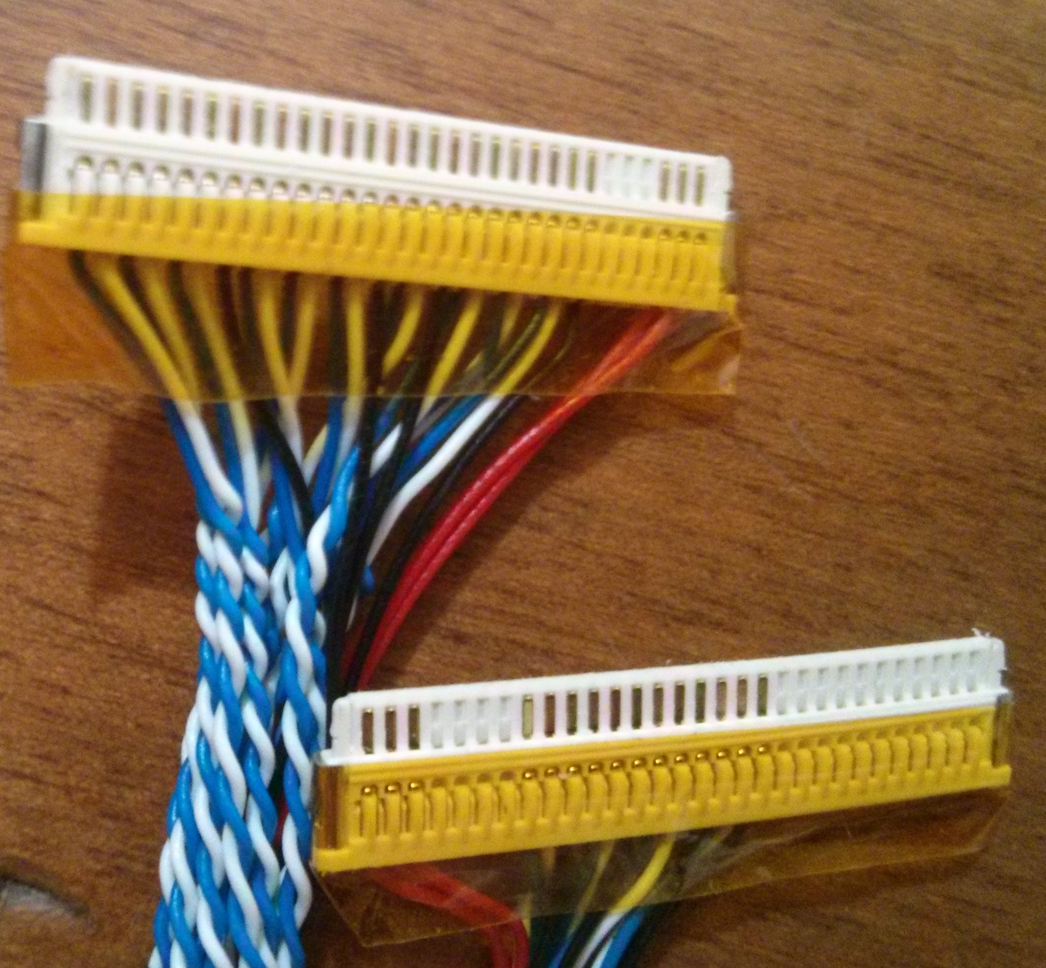
How To Rewire A Lvds Cable Electrical Engineering Stack Exchange
LVDS eDP 32 35 40 45 50 54 Level [dBµV/m] 1G 2G 3G 4G 5G 6G Frequency [Hz] LVDS eDP • LVDS shows higher EMI profile up to 1GHz. • eDP margins very good, 4 dB+ <1 GHz, and 8 dB+ >1 GHz. • EMI doesnʼt align to pixel clock harmonics. • LVDS may have more cable radiation; higher LVDS EMI may be due to longer and tighter

20 Pins Lvds Cable Cable 20 Cable Lvdscable 20 Pin Aliexpress
• LVDS Connection Diagram • Body Connector specifications • Car Compatibility Chart • Activation by original buttons of Audi • DIP Switch Settings • Settings 1. Enter into the setting menu 2. HDMI mode settings 3. NAVI mode settings 4. Rear view camera settings 5. AV1(Front view camera) settings 6. ...
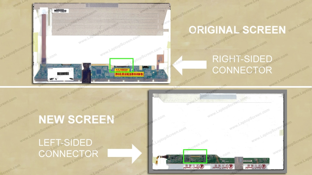
How To Install An Lvds 40 Pin Ribbon Extension Cable For Led Panel Left To Right Connector Laptopscreen Com
System Diagram Figure 1 shows a typical connection with LVDS transmitters and receivers. Host Controller Target Controller DB2 DBn Power PowerBalanced Interconnect SN65LVDS31 SN65LVDS32 Host Target Indicates twisting of the conductors. Indicates the line termination circuit. DBn-1 DBn-2 DBn-3 DB1 DB0 TX Clock RX Clock DBn DBn-1 DBn-2 ...

Block Diagram Of The Swift Test Board The Lvds Signals And The Control Download Scientific Diagram
Single-ended signaling is a simple and common way of transmitting an electrical signal from a sender to a receiver. The electrical signal is transmitted by a voltage (often a varying voltage), which is referenced to a fixed potential, usually a 0 V node referred to as "ground." One conductor carries the signal and one conductor carries the ...

What Is Lvds Cable In Lcd Led Tv And How To Match It Dip Electronics Lab
The MCIB-16 is an LVDS interface board designed to provide the ... The Gate Off Voltage is set by D2 at -6.8V (please, see circuit diagram).

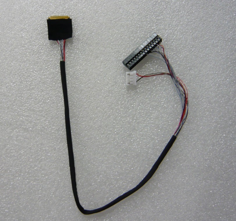
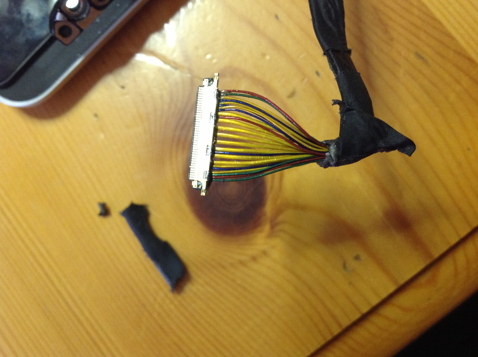
Fixing Lvds Cables For Ccfl Lcd Screens
Dual-LVDS Trigger Kit CIO-8600-DLVDS-TRG 2 TTL triggers for use with Dual-LVDS encoder inputs (use with CIO-8600-DLVDS) 1 Wiring block 195-0330 1 Extension cable 185-0334 General Purpose I/O CIO-8600-GPIO 2 TTL trigger inputs 2 TTL strobe outputs 8 opto-isolated input lines 8 opto-isolated output lines 2 Wiring blocks 195-0330 2 Extension ...

Zivy0 Lvds Cable Dc02001vl00 Rev 2 0 Lenovo Yoga 2 13 Lcd Led Screen Cable
LVDS header pins 25-28 can supply a voltage level of 3.3 V (default), 5 V or 12 V by properly setting the LVDS panel voltage selection jumper, comprised of a 2 x 3, 2.00-mm pitch red header with a black jumper, keyed at pins 1 and 5.

Dell Inspiron 15r 3521 3537 5521 5535 5537 V2521d Lcd Lvds Cable Dc02001mg00 Wit Computers
Analogue signal splitter design balanced audio three channel circuit rf distribution diagram of the amplifier using splitting lvds technique cn0264 note analog devices Proposed Configuration For The Analogue Signal Splitter Scientific Diagram Opa1652 Design Balanced Audio Signal Splitter Circuit By Using Forum Ti E2e Support Forums Proposed Configuration For The Analogue Signal Splitter ...

Universal Lvds Ribbon Cable Marc Defossez 12 Th
The SN65LVDS33 is a TIA/EIA-644standard compliant LVDS receiver. The SN65LVDS33 receiver incorporates the widest common-modeinput voltage range of - 4 V to 5 V, as well as an active-failsafe

Solved I Need To Run 2 Jumper Wires From My Lvds Connector On My Logic Board Imac Intel 27 Emc 2390 Ifixit
If you have a 1280x800 panel, chances are, it's using this pinout. Suitable cable. B: FI-X 30-pin connector dual-lane 6-bit pinout. [TODO: ...
-700x700.JPG)
20455 40p D6 Lvds Cable 40 Pin 1ch 6bit 0 5mm Pitch For Led Lcd Panel Controller
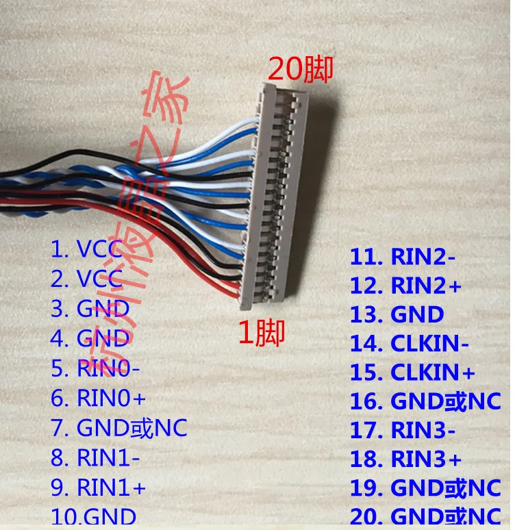
Positive LVDS differential data input : 11: RIN 1-Negative LVDS differential data input : 12: RIN 1+ Positive LVDS differential data input: 14: RIN 2-Negative LVDS differential data input: 15: RIN 2+ Positive LVDS differential data input: 17: CLKIN-Negative LVDS differential clock input : 18: CLKIN+: Positive LVDS differential clock input : 20 ...
1
Proper insulation is required when attaching to the LCD panel directly. ○ Caution. Be sure that LVDS wiring should be thick enough to deliver ...
1
RZ/A2M Group Guidelines for LVDS and MIPI Board Design R01AN5280EJ0100 Rev.1.00 Page 5 of 12 Dec.23.19 2. Transmission Lines The transmission lines are expressed as the wiring pattern that connects RZ/A2M to the LVDS connector and the wiring pattern that connects RZ/A2M to the MIPI connector.
20 Pins Lvds Cable Cable 20 Cable Lvdscable 20 Pin Aliexpress
From this simple diagram in Figure 1-2, the advantages common to all ... using multiple serial data and clock pairs requires careful wiring and low ...
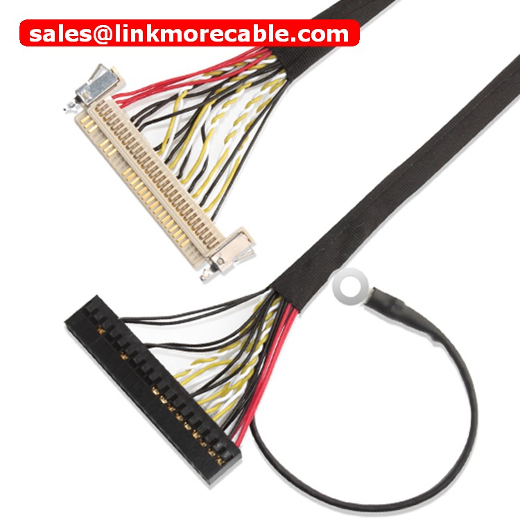
Lvds Cable 30 Pin Lvds Cable To Edp Cable Lcd Lvds Cable40 Pin Ribbon Extension Cable Linkmore
The diagram above illustrates the use of the Chipset (Tx/Rx) in a Host to LCD ... This feature enables you to overcome cable capacitance through the LVDS ...
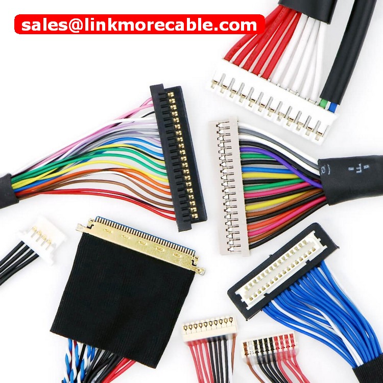
Lvds Cable Assemblies Used For Lcd Led Panel Lvds Cables Display Interface Linkmore
1.2VDS - Low-Voltage Differential Signaling L The 350 mV typical signal swing of LVDS consumes only a small amount of power and therefore LVDS is a very efficient technology, delivering performance at data rates up to 3.125 Gbps. The simple termination, low power, and low noise
40 Pin General Digital And Lvds Headers As Placed On The Schematic Download Scientific Diagram
Wiring diagram for BMW CIC A. Screen unit-replace the OEM screen. B. Power and audio connectors-connect to the OEM head unit (NOTICE the fiber optics plug, see the next page). C. Connect to original harness which unplug from OEM head unit. D. LVDS plug-connect to the LVDS cord which removed from OEM screen (NOTICE if you don't

Mini Edp Cable Sgc Cable Mcc Cable Mcx Cable I Pex Cable Intel Dn800mt Mainbaord Lvds Cable Edp Cable Custom Cable Cable Oem Cable Assembly Lcd Cable Round Cable Ipex Cable 20455 040e 20474 030e 20525 030e Aces 88441 Aces 91209 01011

Led Stage Light Auto Part Wiring Diagram Vga Cable Lvds Cable China Led Stage Light Auto Part Wiring Made In China Com

Universal Lvds Cable Pin Functions And Datasheet In Hindi Youtube Electronics Projects Cable Function

China Led Stage Light Auto Part Wiring Diagram Vga Cable Lvds Cable China Led Stage Light Auto Part Wiring

Lvds Signal Jitter Cable Length And Data Rate

Lvds Connection Diagram For Big Screen Mercedes Android Gps Navigation Hifimax
B133ew07 V 2 Led 20474 30p 0 4mm D6 1 Channel 6 Bit Lvds Cable B133ew07 V 2 Led 20474 30p 0 4mm D6 1 Channel 6 Bit Lvds Cable
Lenovo Lvds Cable Flexibel Thinkpad T410 T410i Series P N 50 4fz06 021 Fru 45m2889 40 Pin New Shopee Indonesia
How To Remake Lvds Cable For Led Lcd Tv Lvds Data Cable Pinout Led Tv Servicing Guide Youtube

Macbook Pro Lvds Ipex Pinout Technical Question Macrumors Forums

Buy 14x Universal Lvds Cable 20 30 40 51pin For 10 65 Lcd Led Panel Screen Test At Affordable Prices Free Shipping Real Reviews With Photos Joom

China Lvds 40 Pin To 30 Pin Manufacturers Suppliers Factory Pricelist Ouke

Lvds Cable Tyco 5 2069715 3 Lvds Cable

Lvds Cable Df14 Series 20pin 1ch 8bit 1 25mm Pitch For A D Board To Lcd

How To Produce A Lvds Cable Custom Lvds Cable Assemblies

Lvds Lcd Panel Kabel Dukungan 20 Pin Df14 Konektor 6 8 Bit Layar Lcd Untuk Dn2800mt D2700mt Dh61ag Dq77kb Pc Papan Utama Suku Cadang Aksesoris Aliexpress
Macbook Pro Lvds Ipex Pinout Technical Question Macrumors Forums

Original New Laptop Display Cable For Asus B451ja B451 14005 01480300 Notebook Vga Cable Screen Lcd Lvds Cable Flex Laptop Display New Laptops Asus

Ampire Lds A62g Cp Smartphone Integration Audi Mmi 2g High Installation Manual Manualzz

Jual Laptop Edp Lvds Lcd Cable Lenovo Yoga 730 15ikb 730 15 Dlzp5 1920 10 Kota Tangerang Ekaakarjayaabadi Komp Tokopedia
Fixing Lvds Cables For Ccfl Lcd Screens
Disesuaikan Kabel Diagram Vga Lvds Cable Assembly Untuk Lcd Papan Buy Lvds Kabel Disesuaikan Lvds Kabel Disesuaikan Lvds Kabel Assenbly Product On Alibaba Com
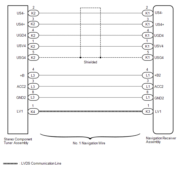
Toyota Tundra Service Manual Lvds Signal Malfunction From Extension Module B1532 B156c Navigation System
0 Response to "45 lvds wiring diagram"
Post a Comment